Solid works Important Terms Uses While Drawing
Introduction:
Solid works is define as a solid
modeling computer –aided design (CAD) that can run on Microsoft windows. It is
also known as “DSS Solidworks”.DSS means the Dassault Systems, the developer of
this CAD software. This is CAD software, which helps to create 2D or 3D solid
models without any complexity, faster and in the cost effective way. The main
advantage of the solid modeler is that very easy to use, Simple Graphics user
Interface and much more friendly, as compare with other CAD solid modeling
software. It contains modeling, Motion, Simulation, Toolbox, Photoview 360,
Scan to 3D, e-drawing and DWG editor.
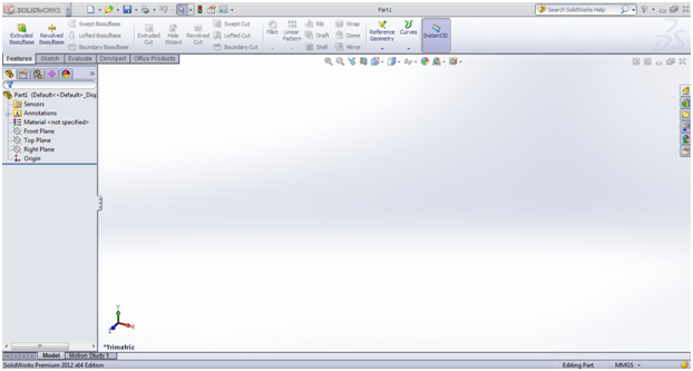
Fig:- Solid
works Part Modeling Interface
- Add Relations – Used to connect related geometry. (Concentric, Collinear, Midpoint, Tangent, Parallel), etc.
- Assembly - An assembly consists of two or more parts mated together. The different parts are called components.
- Auxiliary View – Displays a plane parallel to an existing edge on a part with true dimensions. Usually tied to one of the principle views.
- Axis – A straight line used for creating model geometry, features or patterns.
- Balloons – Balloons are numbers in circles used to identify components in an assembly layout. They are connected to the component by a bent leader.
- Base Feature – The first feature created. Serves as the foundation for the part. Usually kept simple.
- Bill of Materials –A parts list. In an assembly drawing it is a table that relates the components depicted by balloons to the part name, part or drawing number and quantity of the part.
- Boss Feature – Any feature added to a base. Center Marks – Two perpendicular intersecting centerlines used to show the center of a hole.
- Center Marks – Two perpendicular intersecting centerlines used to show the center of a hole.
- Centerline – A working line used for mirroring geometries or for setting certain features. Centerlines do not appear in the final model.
- Chamfer - Removes sharp edges or corners from a feature or part by angling the edge with a flat face.
- Circular Pattern – Creates a circular pattern of a seed diagram in a feature or a sketch. A temporary axis is required to create the pattern.
- Clearance Hole – A nontapped hole for a screw to pass through. The hole is slightly larger thant the screw’s major diameter.
- Collapse – The opposite of explode. Returns an exploded assembly view back to its normal state.
- Component – A part or subassembly within an assembly. Conformation Corner: When in a sketch the upper right corner becomes a purple arrow and red X designating that a sketch is open.
- Construction Line – To create a construction line (other than a centerline) in a sketch, draw the entity. In the property manager check the “For Construction” box and it will change into a construction line which will not be included in the object.
- Control-Drag – Holding down the control key while dragging an object. Used to copy a feature or a dimension.
- Control Tab – When several windows are open at once use control-tab (hold down the control key and press the tab key) to cycle through them. Keep holding the control key down and you can select the part, assembly or drawing you wish from the selection window which appears.
- Cosmetic Threads – This is the simplified threads representation in SolidWorks. It is found through the menu Insert/Annotations/Cosmetic Threads.
- Detailed View – An enlarged area of an existing view. Used to show fine details in a part. Diameter Dimension – When you have a part which is created by a revolution about an axis, do all dimensions across the center line. After rotation they will become diameter dimensions.
- Dimensions – Used to completely define a sketch before extruding or cutting.
- Dimension Tool – Used to enter dimensions into a sketch.
- Dome – Creates a dome on top of a plane end. It may be elliptical, circular, non-elliptical, convex or concave.
- Drawing – One of the three types of files for SolidWorks. This is used to present the working presentations of a part or an assembly. Parts are usually displayed as three view drawings on a title block.
- Draft Angle – The degree of taper applied to a face. Applied to parts which are molded or cast.
- Drawing Template – Contains the title block for each type of layout used. For this course, they will be size A (letter) in either portrait or landscape layouts.
- Edit Sheet Format Mode – In a drawing, this is used to update and add features to the title block. Note: Any drawings are suppressed (disappear) when this mode is active. They will reappear when you exit this mode.
- Edit Sheet Mode – In a drawing used to add and modify the views of a part, add dimensions, geometric dimensions, notes and special views.
- Edit Sketch – To amend a sketch of a feature, right click on the feature in the Feature Manager and select edit sketch.
- Exploded View – An assembled set of components may be exploded to show how all the parts fit together.
- Extruded Base – First 3-D part of any part using a sketch. Extruded Boss – Adding material to a part using a sketch.
- Extruded Cut – Removing material from a part using a sketch.
- Face – A selectable area of a model or feature.
- .Feature Manager – The tree on the left side of the screen which shows all the individual features in the order they were created. It allows one to select and revise any detail of the part or assembly.
- Features – Building blocks of any part. Features add or remove material to a part. They are created from either a 2-D sketch or from existing geometry.
- Fillet – Removes sharp edges from a feature or part by rounding the edge. Cosmetic fillets are usually done at the end of the drawing. Make the fillets with the larger radii first. Include all multiple fillets with the same radii in the same command. Both fillets and rounds are created through the fillet command.
- Fill Screen – Typing an f forces the object to fill the screen.
- First Angle View – This is the primary three view mode in Europe. It consists of the bottom, front and left views.
- Geometric Relations – To force certain behaviors or restrictions on the sketch element. Some available relations are: Horizontal, Vertical, Perpendicular, Parallel, Tangent, Intersection, Coincident, Midpoint, Concentric .
- Graphics Area – The area where parts, assemblies or drawings appear.
- Helix/Spiral Curve – A helix is a curve with a pitch. The curve is created about an axis. Hole Callout – Automatically creates the proper note to dimension a hole created with the hole wizard with the proper symbology and dimensions.
- Hole Wizard – Used to create specialized holes in an object. Can produce simple, clearance, counterbored, countersunk and tapped holes.
- Instance – An item in a pattern or component that appears more than once in an assembly. Layers – Layers may be defined in drawings only. They allow one to place different entities in different layers which may be turned off at will.
- Leader Line – A line connecting a dimension or note to its particular feature. Usually a leader line is constructed of a bent line headed by an arrow.
- Linear Pattern- Creates a linear 2 dimensional array of a seed diagram in a feature or a sketch. The array is made parallel to one or two sides of a feature.
- Loft Feature – A Loft creates transitions between two or more profiles, each on a different plane. A loft boss/base adds material while a loft cut removes material.
- Mates – Geometric relationships that define how various parts are aligned and fit together in an assembly.
- Mirror – A copy of a selected feature reflected about a plane or planar face. In a sketch it is a copy of a sketch entity reflected about a centerline.
- Model – The 3-D solid geometry in a part or assembly document.
- Model View – This is used to include another view besides the standard three. It may be isometric, back, bottom, left, etc.
- Modify Dimension – Double click on a dimension while editing a part sketch to modify a dimension.
- Mouse Center Wheel – To zoom in or out roll the center wheel. To pan hold down the control key with the center button. To rotate a part or assembly, push down the mouse wheel and move the mouse. To pan hold down both the control key and the mouse wheel and then move the mouse.
- Notes – Adds text to a drawing. May be used with leaders or as just plane text. If an edge, face or vertex was selected prior to adding the note, the leader will be attached to the selected feature.
- Open Profile – A sketch or sketch entity with endpoints exposed. Options: Tool Menu – Sets all the parameters for the part or drawing. Things such as units, number of decimals, fonts, tolerances, etc.
- Origin – Represents the 0,0,0 point in a model. In a active sketch, it represents the 0,0,0 point of that sketch.
- Part – One of the three main files of Solid Works. It is here where each individual item is created. Only one solid contiguous object is allowed in a part file.
- Pattern – Creating a linear pattern or a circular pattern in two or three dimensions.
- Plane – Used to define the flat surface on which to sketch. The three default planes are Front, Top or Right. Other planes may be defined using the plane tool.
- Property Manager – The tree on the left side of the SolidWorks window used for editing sketches and definitions of entities.
- Rebuild – After any changes in a sketch or definition, the part must be rebuilt before proceeding.
- Relation – A geometric constraint between entities in a sketch or with axes, edges or vertices..
- Revolved Base/Boss – Adds material to a feature by means of revolution. It requires a centerline and a sketch on a sketch plane. This may be a complete revolution or any angle defined.
- Revolved Cut - Removes material to a feature by means of revolution. It requires a centerline and a sketch on a sketch plane. This may be a complete revolution or any angle defined.
- Rib – Adds material between contours of existing geometry. Ribs add structural integrity to a part without adding much mass.
- Section View – Shows the internal cross section of a part, component or assembly and shows an interior feature. These may be done anywhere in a component.
- Seed Diagram – A feature or group of features which are used as input to a feature tool such as linear patterns, circular patterns or a feature mirror.
- Selection Tool – An arrow used to select individual parts of a feature for mating or geometrical relations. Hit the escape key to enter the select mode or click on the select icon. Select Other – If you cannot get the right entity to select, right click on one, choose other and right click until the correct entity is selected, then left click. Shaded View – Displays the model as a colored solid.
- Sheet Format – In a drawing the sheet format includes the title block, page size orientation, standard text, borders and so on.
- Shell – A shell tool takes a solid object and makes it into a thin-walled object.
- Sketch – A 2-D profile of a feature. Sketches are created on a flat plane or face within a model.
- Sketch Colors – The lines of a sketch change colors to show how well the feature is defined. Blue implies under defined, black means fully defined, red means it is over defined and yellow means impossible geometry.
- Sketch Mirroring – Used with a centerline while producing a symmetrical sketch. When invoked anything drawn on one side of the centerline can be mirrored to the other side. Only half the object needs to be dimensioned as the mirrored objects will reflect any changes in the original.
- Smart Mates – Mates that are automatically invoked when a component is placed into an assembly. These are concentric or coincident mates.
- Sub-assemblies – An assembly which is used in a higher assembly just like another part. Suppressed – When a feature or component is suppressed, it is not shown on the screen. This gets the feature out of the way during an operation. The feature or component may be unsuppressed at any time and it will reappear.
- Surface – A zero thickness planar or 3-D entity with edge boundaries often used to create solid features.
- Sweep – Adds or removes material along a predefined line. A sweep needs at least a profile sketch and a path sketch.
- System Feedback – While drawing or positioning objects, the cursor changes its look, giving feedback on what it is pointing at or details about what is being drawn.
- Third Angle View – The standard three view mode in the USA. It consists of the Front, Top and Right views. This is the default for Solid Works.
- Three View – Standard front, top and right views in a drawing.
- Title Block – Each company has its own unique title block. On drawings, this gives all the relevant information about the part, i.e. name, part number, date, tolerance, name of drawer, scale, material, revisions, etc.
- Tolerance – The difference between the maximum and minimum variation in a dimension. Transparent Tool Bar – The icons found at the top of the work area which may be used to control the views and shadings of the part of assembly. Trim – Used to cut away extra parts of lines.
- Under Defined – A sketch is under defined when there are not enough dimensions or relations to prevent entities from moving or changing size.
- Vertex – A point where two or more lines or edges intersect.
- Wireframe View – A view where all edges are visible. The model is transparent.
- Sketch Tools – The common tools used in creating a sketch. They may be used in any combination to complete a sketch.
- Arc – A circular segment.
- Center Point – Click on the center of the circle, drag out to the start of the arc and then drag the arc.
- Tangent – Used after drawing a line. Click on the end of the line and drag the arc to the other side. A dotted line shows when the arc makes a 180° angle.
- Three Point – Pick three points (the two end points and then a point in the center) on the arc to define it.
- Circle – Draws a complete circle, by clicking on the center and dragging out to the required radius.
- Convert Entities – Used to take existing geometries from one sketch and bring it into the current sketch. The geometries are related so if the dimensions of the original geometry are changed, the converted entities will change as well.
- Extend – Extends a line to meet a certain point.
- Line – Draws a series of straight lines by clicking on the start point and dragging to the end point.
- Offset – Allows certain geometry to be offset a given amount to duplicate the geometry with different dimensions.
- Parallelograms – similar to the rectangle except that the sides do not have to perpendicular. If the control key is held down when dragging, a rectangle at an angle may be drawn.
- Point – Allows points to be defined to which other geometry may be attached.
- Polygon – Is used to create inscribed or circumscribed polygons by defining the number of sides, the center and radius of the defining circle.
- Rectangle – Creates a rectangle with the necessary geometrical relations included. Can be a corner rectangle, center rectangle, 3 point corner rectangle, 3 point center rectangle or parallelogram.
- Spline – A complex curve made up of three or more defining points.
- Trim – Used to cut away extra parts of lines.


Comments
Post a Comment